
Offshore wind and supply chains
Offshore wind farms in Poland: opportunities for steelwork suppliers
Offshore wind farms in Poland have entered the construction and installation phase, with Polish plants already supplying nacelles, cables, offshore-substation structures, foundation equipment and secondary steel. For most subcontractors, however, the strongest opportunity does not lie in complete foundations. It lies in clearly defined packages covering access systems, auxiliary steelwork, temporary works and equipment for operations and maintenance bases.
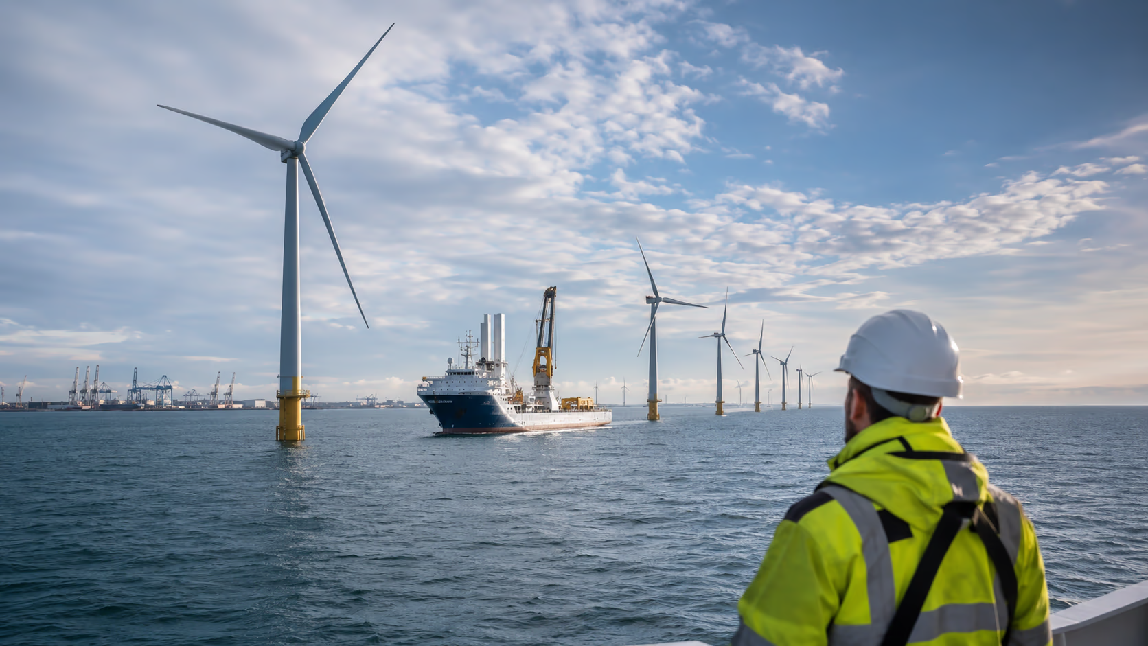
Poland’s offshore sector has moved into construction and installation
Baltic Power, developed by ORLEN and Northland Power, remains the most advanced project. The wind farm has a maximum installed capacity of 1,140 MW and comprises 76 turbines. When first power was achieved on 10 July 2026, 54 turbines had been installed, while further installation and commissioning were still under way. Northland Power referred to commercial operation in the second half of 2026, while ORLEN communicated completion of construction in autumn 2026. [1] [2] [3]
Baltica 2, developed by PGE and Ørsted, has a capacity of 1,498 MW and will comprise 107 turbines. The final investment decision was taken on 29 January 2025, and an offshore installation campaign covering 111 monopiles began in May 2026. Full commissioning is planned by the end of 2027. An exact date for first export of electricity to the grid has not been announced. [5] [6]
Bałtyk 2 and Bałtyk 3 are being developed in parallel by Equinor and Polenergia. Each project has a capacity of 720 MW, and the two wind farms will comprise a total of 100 turbines. Final investment decisions were taken on 19 May 2025, while financial close was announced separately on 22 May 2025. In August 2026, the investors reported that foundation installation had reached the halfway point. Commissioning is planned for 2027, followed by full commercial operation in 2028. No exact first-power date has been published. [8] [9] [10] [11]
Project status and relevance to the supply chain
| Project | Capacity | Status as at 6 August 2026 | Supply-chain relevance |
|---|---|---|---|
| Baltic Power | 1,140 MW | First power exported; installation of the remaining turbines and commissioning still under way. | Confirmed Polish supplies include nacelles, secondary steel, cables, substation structures and service infrastructure. |
| Baltica 2 | 1,498 MW | Onshore and offshore construction in progress; monopile installation started. | More than 400 additional foundation structures were manufactured largely in Poland. |
| Bałtyk 2 | 720 MW | Foundation installation and infrastructure works in progress. | A joint supply programme with Bałtyk 3 includes transition pieces, substations and an O&M base. |
| Bałtyk 3 | 720 MW | Being delivered in parallel with Bałtyk 2. | Transition-piece secondary steel is manufactured in Poland, while other work is divided internationally. |
The financial scale of Bałtyk 2 and Bałtyk 3 illustrates the size of the programme, but the figures communicated by the project partners cover different scopes. Polenergia described the combined investment value as approximately PLN 27 billion excluding financing costs, while Equinor referred to approximately EUR 7.2 billion in capital expenditure and other costs financed during construction. These are not identically defined measures and should not be compared or converted directly. [8] [9]
Polish manufacturing participation is real, but package-specific
Baltic Power estimates a minimum Polish contribution of 21 per cent over the wind farm’s entire life cycle, from project development to decommissioning. This figure does not mean that 21 per cent of the value of steelwork or construction activity was automatically placed in Poland. It refers to the wider project life cycle and must be interpreted in accordance with the scope used by the developer. [3]
Baltic Power
Confirmed Polish supplies include turbine nacelles manufactured by Vestas in Szczecin, onshore cables supplied by Tele-Fonika Kable in Bydgoszcz and steel structures for two offshore substations fabricated in Gdynia and Gdańsk by Grupa Przemysłowa Baltic. Smulders plants in Żary, Niemodlin and Łęknica manufactured foundation secondary steel. An operations and maintenance base was also built in Łeba and commissioned in April 2025. [1] [3] [4]
Baltica 2
A package comprising more than 400 additional foundation structures was confirmed, including external working platforms and other secondary-steel components. The principal part of this package was manufactured in Poland, and the completed components were shipped to the installation port in Rønne. This does not mean that complete monopiles were manufactured in Poland. [7]
Bałtyk 2 and Bałtyk 3
Sif is responsible for the main tubular sections and flanges manufactured in Roermond in the Netherlands. Smulders is delivering secondary steel, coatings, electrical systems and testing, with the secondary-steel components being produced at Polish plants. Final assembly of the transition pieces takes place in Hoboken, Belgium. [12]
International division of work
For Baltic Power transition pieces, the primary-steel sections were manufactured at Haizea Bilbao. Secondary steel was produced in Poland, while final assembly and outfitting were carried out in Newcastle. This model demonstrates that Polish participation can be substantial even when the completed component is not integrated at a single Polish facility. [4]
Primary steel, secondary steel and temporary works require different capabilities
Primary steel carries the principal structural loads. It includes monopiles, the main cylindrical sections of transition pieces, large-diameter flanges, principal jacket components and the main load-bearing structures of offshore substations. Manufacturing these components requires the rolling of very thick plate to large diameters, long longitudinal and circumferential welds, advanced automation and the handling of elements weighing hundreds or thousands of tonnes.
Large production halls, heavy-duty overhead cranes, extensive storage areas and usually direct quayside access are required. The ability to weld thick plate or operate a plate-rolling machine is not enough if the plant cannot move, turn, coat and dispatch the finished component.
Permanent secondary steel comprises components permanently installed on a foundation, transition piece or substation that do not form the principal load-bearing shell. Typical examples include crew-access systems, ladders, platforms, stairs, handrails, gratings, guards, cable brackets and equipment foundations.
Temporary works are used during manufacturing, storage, transport and installation but do not remain on the wind farm. Transport frames, lifting structures, storage stands and cradles should not automatically be described as secondary steel because their design is driven mainly by lifting loads, road and sea transport, stability and interfaces with port or vessel equipment.
Differences between the main steelwork categories
| Category | Role and examples | Main manufacturing barriers | Realistic supplier profile |
|---|---|---|---|
| Primary steel | Monopiles, main transition-piece sections, large flanges, principal jacket components and main substation structures. | Thick plate, large diameters, extremely high component weights, heavy cranes, extensive facilities and port logistics. | A limited group of large, specialised fabricators. |
| Permanent secondary steel | Boat landings, ladders, platforms, stairs, handrails, brackets, J-tubes, equipment foundations and internal fittings. | Geometry, distortion, interfaces, welding, coatings, documentation and complete-module control. | Medium-sized and large plants, together with selected SMEs operating as Tier 2 or Tier 3 suppliers. |
| Temporary works | Transport frames, storage stands, cradles, lifting structures and assembly fixtures. | Transport and lifting loads, lifting points, stability, load testing and operating instructions. | Plants capable of producing heavy frames and controlling critical interfaces. |
Which packages can Polish suppliers manufacture?
Manufacturers of secondary structures, auxiliary modules and installation equipment form a much broader potential supply base than primary-steel producers. These packages remain technically demanding, but they do not always require infrastructure comparable to a monopile factory.
Typical packages, supplier profiles and entry routes
| Package group | Typical components | Potential supplier profile | Typical entry route |
|---|---|---|---|
| Access systems | Boat landings, ladders, platforms, stairs and handrails. | A medium-sized or large plant with tubular-steelwork experience. | Tier 2 supply to a transition-piece manufacturer. |
| Platforms and internal fittings | Gratings, walkways, holders, brackets and equipment foundations. | An SME or medium-sized manufacturer with well-organised repeat production. | Build-to-print production or module supply. |
| Cable routing | J-tubes, clamps, supports, guides and pull-in arrangements. | A plant with controlled tube bending and accurate assembly capability. | Supply to a foundation manufacturer or cable contractor. |
| Offshore-substation modules | Equipment frames, skids, pedestals, platforms and guards. | A medium-sized or large plant combining fabrication with machining. | Subcontracting for a substation integrator. |
| Temporary works | Transport frames, lifting structures, cradles, stands and fixtures. | A plant capable of fabricating heavy frames and controlling lifting points. | Supply to a fabricator, port operator or installation contractor. |
| O&M bases and equipment | Walkways, racks, workshop modules, storage equipment and deck equipment. | An SME or medium-sized manufacturer with flexible production capacity. | Direct supply, retrofit work or short production runs. |
Boat landings: control of the complete geometry
A boat landing enables personnel to transfer safely from a service vessel to a turbine or foundation. Its manufacture requires control of the complete tubular geometry, the position of fenders, ladders and platforms, and the alignment of all connection points with the primary structure. Inspection cannot be limited to the quality of individual welds.
J-tubes: bending, alignment and cable interfaces
A J-tube is a curved pipe used to guide and protect a power cable as it enters a foundation or substation. Weld quality alone does not determine whether the component is acceptable. An incorrect bend radius, alignment error or misplaced support may prevent cable pull-in or the installation of the complete module.
Temporary works: temporary does not mean non-critical
Transport frames, lifting structures, storage stands and cradles may require engineering calculations, load testing, safe-working-load markings and detailed operating instructions. This is a separate order category that can be accessible to specialist subcontractors but requires deliberate control of lifting and transport risks.
Technology, facilities and logistics must match the component
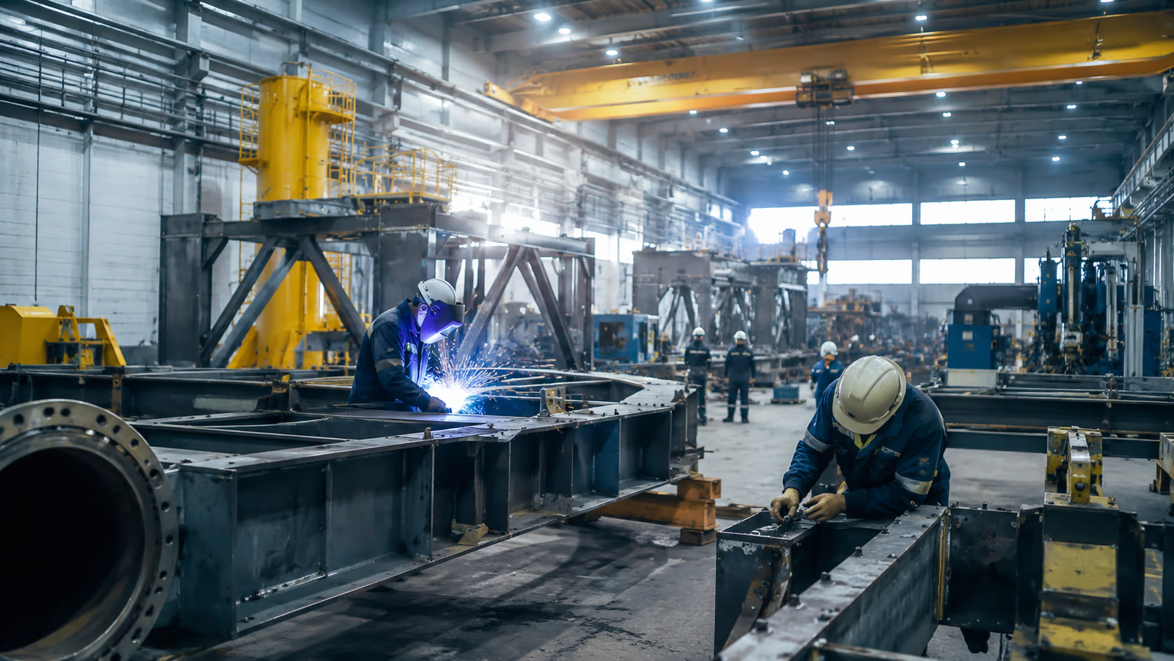
A plant assessment should not begin with the question of whether a company “manufactures steel structures”. It should begin by matching the requirements of a defined package against the practical limits of each production process. The same machine may be adequate for small brackets but unsuitable for a complete platform or tubular assembly.
Cutting and edge preparation
Laser cutting may be efficient for brackets, holders, platform parts and components made from thin or medium-gauge plate. Plasma or oxy-fuel cutting is more common for thick stiffeners, large frames and heavy welded structures. Buyers should verify table dimensions, edge quality, bevel-cutting capability and process repeatability rather than relying solely on the maximum quoted plate thickness.
Tubular work, rolling and bending
Tubular structures require controlled end preparation, bevelling, angled cutting and maintenance of the relative position of individual sections. A fabricator should be able to work from three-dimensional models, use appropriate assembly fixtures and measure the complete structure. Plate rolling and bending capability must be assessed in terms of working length, machine force, bend radii, springback compensation and repeatability across the production run.
Welding and distortion control
MAG is normally the primary welding process for carbon-steel structures. TIG may be required for stainless steel, smaller pipe diameters, root passes or joints requiring closer control. Submerged-arc welding is mainly justified for long, repetitive welds in thick-plate structures. In practice, the result often depends more on welding sequence, shrinkage prediction, datum positioning, intermediate measurement and controlled straightening than on the welding process alone.
Post-weld machining
Equipment foundations, crane bases, winch foundations and skids may require milling, boring or drilling after welding to achieve the required flatness and hole position once stresses have been released. The statement that a manufacturer has a CNC machining centre is not enough. Its working envelope, component-weight limit and ability to accommodate the complete assembly must be confirmed.
Cranes, access doors and assembly space
Door dimensions, crane-hook height, the lifting capacity of individual bays and the ability to rotate a structure can disqualify a plant that appears to have all the required production technologies. A structure that fits the welding station may not pass into the blast room or paint booth. Space is also needed for trial assembly, scanning, rework, documentation completion and temporary storage.
Transport and quayside access
Quayside access is an advantage for large modules, but it is not essential for every package. Smaller structures may be transported by road if the manufacturer has a verified abnormal-load route, suitable lifting points and an effective coating-protection method. Splitting a structure into modules is reasonable only if it does not compromise final assembly or interface control.
Certificates open the discussion, but they do not replace quality, documentation and coating capability
EN 1090 and ISO 3834-2 in a project-specific context
EN 1090 may apply to structural steel components covered by the relevant specification. EXC3 or EXC4 may be required for selected packages. It should not be assumed, however, that every platform, transport frame, guard or item of equipment is subject to identical requirements. An EN 1090 certificate does not in itself confirm the ability to manufacture boat landings, J-tubes or offshore-substation modules. [16]
ISO 3834-2:2021 defines comprehensive quality requirements for the fusion welding of metallic materials. Here too, certification is only one part of the assessment. Procurement teams should verify the scope of the approved processes, personnel qualifications, welding coordination, consumables management and the handling of non-conformities. [13]
Manufacturing and acceptance documentation
A typical documentation package may include:
- approved welding procedure specifications and the corresponding welding procedure qualification records;
- welder and operator qualifications covering the relevant processes, materials, positions and thicknesses;
- a welding plan, work sequence and distortion-control plan;
- weld maps linking each weld to its procedure, operator and inspection result;
- material traceability from the 3.1 inspection certificate to the finished component;
- an inspection and test plan with hold, witness and review points;
- visual, ultrasonic, magnetic-particle or penetrant-testing reports;
- dimensional inspection records and three-dimensional scanning results where required;
- surface-preparation and coating-application records;
- a register of non-conformities, repairs and approved concessions;
- a final manufacturing data record, as-built documentation and acceptance dossier.
NDT must be determined by the function of the weld
The scope of non-destructive testing should not be defined by a generic rule such as “100 per cent ultrasonic testing for offshore”. The method and inspection frequency depend on the weld function, material, geometry, load level and project documentation. Visual testing forms the basis of inspection. Ultrasonic testing is primarily used to identify internal discontinuities in suitable joints, while magnetic-particle and penetrant testing are used for surface examination.
Corrosion protection may be a greater barrier than welding
Components installed offshore operate in a highly corrosive environment. Requirements may refer to the ISO 12944 series, the CX atmospheric-corrosivity category, immersion categories, expected coating-system durability or an owner-specific specification. NORSOK may apply where required by the contract, but it is not automatically the governing standard for every offshore structure. [14]
The older C5-M designation should not be copied automatically into new requests for quotation. Current specifications may distinguish between atmospheric and immersed environments and define separate systems for different areas of the same component.
The surface-protection process may include edge rounding, weld-spatter removal, abrasive blasting, dust and soluble-salt checks, thermal metal spraying, stripe coating and multi-layer epoxy and polyurethane systems. Records should confirm substrate temperature, dew point, relative humidity, overcoating intervals and the thickness of each coat.
Qualification should also establish whether surface preparation and coating are performed in-house or by a subcontractor. Replacing an approved paint facility or coating system with an alternative described by the manufacturer as equivalent may require formal customer approval.
DNV standards may provide the basis for the design, verification or certification of specific wind-turbine support structures. This does not mean that every bracket, platform or secondary-steel component requires an individual “DNV approval”. The required assessment scope follows from the contract and the project’s certification model. [15]
Supplier sourcing should begin with a clearly defined package
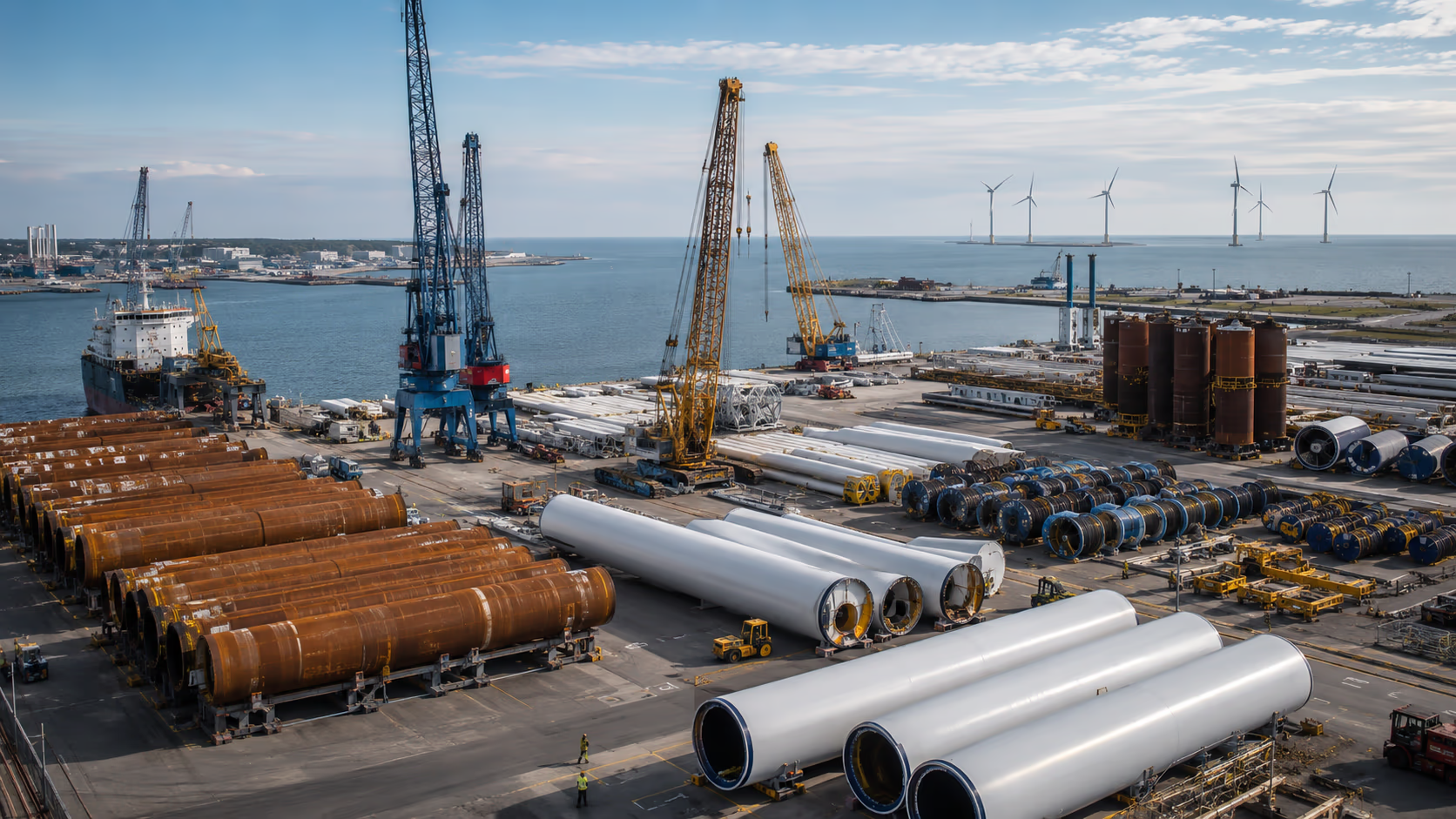
A general search for “offshore steelwork manufacturers” usually produces a list of companies whose capabilities are difficult to compare. The procurement process should begin with a definition of the component, the boundaries of responsibility and the technical conditions, and only then move to market mapping.
Define the boundaries of responsibility
Buyers must establish whether the supplier is responsible only for manufacturing from customer documentation or also for shop design, material procurement, engineering calculations, inspection, surface protection, equipment installation, transport and final documentation. A build-to-print model limits the manufacturer’s design responsibility, but it does not remove the need for a manufacturability review, clash reporting or revision control. A scope including shop design requires additional engineering capability and disciplined document management.
Define dimensions, weight and interfaces
The enquiry should state the maximum weight of a single item, transport dimensions, material grades and thicknesses, required machining operations, and surface and hole tolerances. Tubular structures also require bend radii, permissible alignment deviations and precise locations for all connection points.
Assign project-specific quality requirements
Certificates, execution classes, NDT scope and surface-protection systems must follow from the contract documentation. Copying the same requirements into every RFQ can restrict competition unnecessarily or create nominal criteria that do not demonstrate the supplier’s actual capability.
Build a longlist around a combination of processes
A defined package may require tube cutting, plate rolling, MAG welding, machining of large datum surfaces, abrasive blasting and painting. For initial market mapping, buyers can use the Metal Navigator search tool for metalworking suppliers in Poland, which allows companies to be filtered by multiple processes, certificates, location and available financial data. The database can support longlist creation, but it does not replace data confirmation, technical prequalification, auditing or project-specific supplier approval.
Conduct a capability screening
The qualification questionnaire should address actual operating limits rather than a catalogue list of machinery. Buyers need information on maximum cutting dimensions and thickness, rolling length, machine working envelopes, crane capacities, access-door dimensions, paint-booth sizes, assembly areas and available storage space.
Audit the production system
During the audit, the team should trace a sample material item from its inspection certificate to the finished structure, confirm the validity of WPQRs and WPSs, review part identification, check welding-consumable control, examine weld mapping and assess the closure of non-conformities. A complete documentation dossier from a previous project of similar complexity is particularly useful.
Approve the first article and the project scope
For a new supplier, a sensible approach is to commission a first article manufactured under enhanced control or a limited pilot series. Trial assembly or a representative mock-up may also be required. Only a positive assessment of the documentation, audit findings and trial delivery supports approval for a defined package.
Qualification should not be transferred automatically from one project to another. Material grades, tolerances, weld classes, coating systems and developer requirements may differ even where the component name remains the same.
A complete RFQ and a staged entry route improve the prospects for SMEs
What should be included in the request for quotation?
The RFQ must allow the manufacturer to assess feasibility and price the risk correctly. A component name and an approximate steel weight are not sufficient. A complete enquiry should include:
- drawings, the bill of materials, component weight, dimensions and tolerances;
- the boundaries of responsibility and all required manufacturing and machining processes;
- the inspection scope and surface-protection specification;
- the required final-documentation list and material-traceability requirements;
- packing arrangements, delivery location, programme and production quantity;
- requirements for first-article production, trial assembly and acceptance;
- rules governing customer attendance at inspections and hold points.
Four levels of supplier assessment
| Stage | What it confirms | What it does not yet confirm |
|---|---|---|
| Supplier identification | Potential availability of the required processes and equipment. | The ability to produce a defined component to the required geometry and quality. |
| Prequalification | Compliance with the basic technical, quality and organisational conditions. | That the processes operate effectively in practice or that documentation is complete. |
| Audit | How production, traceability, inspection and non-conformity processes operate in practice. | Approval for every material, drawing and coating system. |
| Project-specific approval | Alignment of the plant with a defined drawing, material, inspection plan, coating system and responsibility scope. | Automatic qualification for another project with different requirements. |
The most accessible route is usually through Tier 2 and Tier 3
A Polish manufacturer does not need to enter the offshore market through a direct contract with the wind-farm developer. For permanent secondary steel, cooperation as a Tier 2 or Tier 3 supplier to a transition-piece manufacturer, offshore-substation integrator or access-system supplier is often more realistic.
An initial scope may include a group of brackets, a single platform, a ladder, a J-tube section, internal equipment or an assembly frame. This allows the customer to test quality and documentation performance without placing an entire module with a new supplier.
Direct orders may be more accessible for temporary works, service-base equipment, storage racks, workshop equipment and selected O&M packages. These structures may be smaller, but they still require documented welding, suitable surface protection, controlled lifting points and appropriate operating documentation.
Cooperation should be expanded in stages. Once the first structure has been completed, inspection comments closed and the manufacturing data record approved, the scope can be increased to a short series, complete module or package with greater technical responsibility.
Risks that do not appear in a machinery list
Financing and contractual exposure
Offshore packages are often large, irregular and vulnerable to design changes. A supplier may need to procure material in advance, reserve a substantial area of the production hall and finance work before reaching the next payment milestone. Guarantees, delay liability, insurance and currency exposure add further risk.
Approved materials and subcontractors
The availability of plate, pipe, grating and other materials from approved sources may become a constraint. Changing the steel mill, grade or material manufacturer may require customer approval. Similar rules may apply to NDT subcontractors, paint facilities and coating-system suppliers.
Short runs and preparation costs
Individual boat landings may differ in geometry, substation modules may have different interfaces, and a transport frame may be used for only one installation campaign. Pricing must cover tooling, documentation preparation, approvals and change risk rather than only steel weight and welding hours.
An excessively broad supplier list
A plant with laser cutting, a welding shop and an ISO certificate may still lack the crane capacity, trial-assembly space, coating control or documentation capability required for the package. For the buyer, an unfiltered supplier list can be as risky as an underestimated price.
What buyers and suppliers should take away
Delivery of Baltic Power, Baltica 2 and the Bałtyk 2 and 3 projects confirms that Polish plants can participate in the manufacture of components for offshore wind farms. Confirmed supplies include foundation secondary steel, substation structures, cables, nacelles and operations and maintenance infrastructure.
The largest and most highly integrated structures remain the domain of plants with heavy-duty cranes, advanced quality systems, large paint facilities and port logistics. For SMEs, platforms, ladders, brackets, cable-routing components, transport frames, base equipment and other modules manufactured from Tier 1 contractor documentation offer a more realistic market.
For an international buyer, this means replacing a generic search for an “offshore manufacturer” with precise sourcing for a defined package. For a Polish supplier, the safest route is to begin with a limited scope, demonstrate the quality of the first article and expand responsibility gradually.
Offshore wind farms in Poland create a genuine opportunity for suppliers, but identifying a company with suitable machinery does not establish its suitability. Only a combination of process-based market mapping, prequalification, auditing, trial production and project-specific approval can distinguish a potential fabricator from a supplier capable of achieving the required geometry, schedule and documentation completeness.
Frequently asked questions
Can a manufacturer with EN 1090 certification automatically supply offshore steelwork?
No. EN 1090 may be one contractual requirement, but the certificate alone does not demonstrate the ability to manufacture a specific offshore package. Buyers must also assess the certification scope, welding procedures, production dimensions, material traceability, inspection, coating, documentation and logistics.
Can a Polish company without previous offshore references manufacture a boat landing?
It may be qualified, particularly as a Tier 2 supplier, if it has relevant experience in tubular steelwork and can demonstrate control of geometry, welding and surface protection. A first contract will usually require an audit, first-article production, enhanced inspection and formal project-specific approval.
Are transport frames classified as secondary steel?
Not necessarily. Transport frames, cradles, lifting structures and storage stands are usually classified as temporary works or installation equipment. They do not remain on the wind farm, and their requirements are driven mainly by lifting, transport, stability and interfaces with port or vessel equipment.
What should be checked before issuing an RFQ to a Polish fabricator?
Buyers should verify the maximum dimensions and weight of the structure, crane capacities, cutting, forming and post-weld machining capabilities, and the dimensions of blasting and painting facilities. Distortion control, material traceability, NDT scope, sample quality documentation and transport conditions should also be reviewed.
Does first power from Baltic Power mean that construction has been completed?
No. When first power was achieved on 10 July 2026, 54 of the 76 turbines had been installed and further installation and commissioning were still under way. First export to the grid is a separate milestone from full commercial operation.
Which offshore packages are most accessible to Polish SMEs?
The most realistic opportunities include defined secondary-steel packages such as platforms, ladders, handrails, brackets, cable-routing components and internal equipment, as well as temporary works and O&M base equipment. Entry into the supply chain will usually take place through a Tier 2 or Tier 3 role, followed by gradual scope expansion after a successful trial delivery.